
Tiny Tetris

All source files for this project are available here: https://github.com/Jianan-Li/Tiny-Tetris
Before talking about the Tiny Tetris itself, I need to say that there are a couple firsts with this project:
First time using the laser cutter to make enclosures.
First time using a stencil for applying solder paste.
First time using a toaster oven to reflow PCBs.
First time using an IC in QFN package with 0.5mm pitch (ATmega32u4).
There are two things I don’t like about my previous Tetris Gaming Device. First, it’s too bulky. It doesn’t fit in my pocket, so I can’t bring it anywhere with me. Second, it’s not rechargeable through usb. The battery used in the Tetris Gaming Device is a 7.4V 2S LiPo battery, so you’ll have to use the special LiPo charger to charge it instead of usb.
That’s why I decided to make the second generation of the Tetris Gaming Device. Introducing the Tiny Tetris!

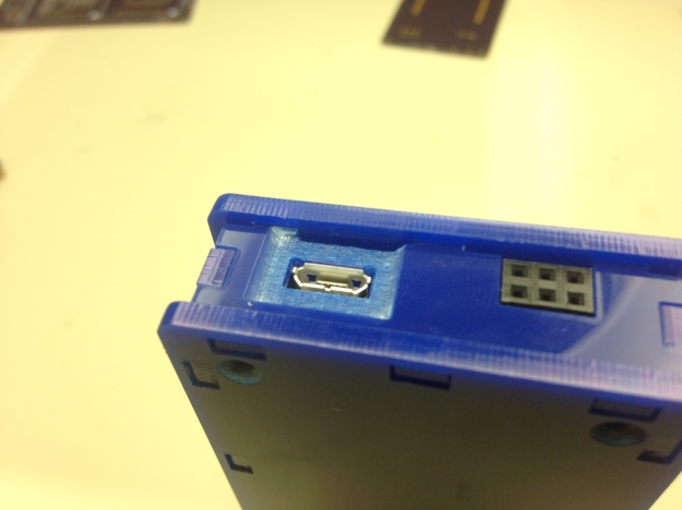
The size of the Tiny Tetris is 94.0 mm (3.70 inches) x 49.5 mm (1.95 inches) x 17.1 mm (0.67 inch). It is powered by a 3.7V LiPo battery and is rechargeable through its micro usb port.

On the left side, there are two general purposes buttons, which I configured to adjust the brightness of the LED display in my demo program, and two indicator LEDs for power and charging respectively.

On the right side, we have a reset button that is connected to the reset pin on the MCU.

On the top, there is a pushbutton power switch. The circuitry used is essentially the same as the breakout board that Adafruit sells.

On the bottom, there is the micro usb port for both charging and programming the MCU (ATmega32u4), and also a 6-pin ICSP/ISP header for flashing the bootloader and setting the fuses with USBTiny or other AVR programmers.
There are a couple things I want to talk about in this post, including the enclosure design, the pcb design and component selection, and then the software.
First, let’s talk about the enclosure design. On the old Tetris, the enclosure is 3D printed on a Stratasys 3D printer. Since I wanted to experiment with different tools and machines in my projects, I decided to laser cut the enclosure for the Tiny Tetris in our student machines shop.

It’s not easy to get the power and speed settings right on a laser cutter, and you’ll have to design the kerf into each piece to get the correct dimensions. The picture above shows about a third of all the tests that I did using scrap acrylic pieces to get everything right.
 The design I used consists of six pieces of acrylic: top, bottom, and the four sides. The side pieces have tabs both on the ends and sides, so all the sides pieces can be connected together, and then plug into the top and bottom pieces. The eight holes and the top and bottom pieces are for the flat head M2 screws. If you look carefully at the screw holes, you’ll see that they are countersink holes. I did this with the 3D engraving feature that is available on the Universal Laser Systems. It turns grayscale images into three-dimensional engravings, so all I have to do to countersink the holes is to draw a circular grayscale gradient around the holes.

I used the same technique to 3D engrave the area around the joystick/navigation switch to allow the movement of the switch without exposing too much circuit board from the top, and also the area around the micro usb port to be able to use any micro usb cable with this device.

The design of the buttons on this acrylic enclosure is inspired by this clock kit from Evilmadscientist. When pressed the acrylic would bend just enough to trigger the pushbutton mounted on the pcb inside.
Here is a picture showing the thickness breakdown and how everything is fastened together.

Next, let’s talk about the pcb design and component selection.


I went through a total of four iterations of the pcb design, and they are named Tetris v1.0 ~ Tetris v1.3 as indicated on the pcb. There is a huge difference between v1.1 and v1.2 since I made the decision to replace the ATtiny85 with the ATmega32u4, whereas the difference between v1.0 and v1.1, and v1.2 and v1.3 is not so significant.
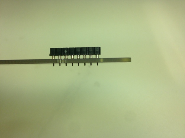
Moving from v1.0 to v1.1, I changed the way that the 8-pin headers are connected to the pcb by increasing the hole size. Here are pictures showing the difference between the two.
 The difference in height between the two is about 1.5mm, which means that it reduced the thickness of the Tiny Tetris by almost 10%.
Moving from v1.1 to v1.2, I decided to replace the ATtiny85 with the ATmega32u4. The main reason is that I realized I wanted to be able to measure the battery voltage and have the device automatically turn off when the voltage is below a certain threshold. This feature requires two more pins – one with ADC to measure the voltage and the other to kill the power – and this means that if I stick with the ATtiny85, some of the pins will have dual functionalities, and it would be even more troublesome to run SoftwareSerial at the same time. So in order to make the device more reliable and function more predictably, I decided to use the ATmega32u4 instead. But this is not a decision that can be made at any time of the day. I was lucky enough to find a small quantity of the ATmega32u4RC available on Digikey. Now if you don’t check Digikey regularly, you probably don’t know that all variants of the 32u4 have been out of stock for months, not only on Digikey but also other major distributors, due to the popularity of the chip. I couldn’t believe it when I accidentally found 71 of the RC version available on Digikey and immediately bought 10 of them.


Also, another change I made to the pcb design is that I added a tiny piece of pcb under the joystick so that it would be able to stick out above the top surface of the enclosure. In v1.1, the joystick is almost impossible to use when the pcb is mounted in the enclosure because it’s not as tall as the LED matrix. So i decided to add a small piece of pcb just for the joystick for better user experience. The two pcbs are aligned using two short pieces of resistor legs before and during the reflow process.
From v1.2 to v1.3, the only thing I changed is the location of the reset button, as I’ve found that it is easier to accidentally press the reset button when it’s located near the top on the right side of the device.

So in the final version, we have a total of five ICs on the board: MCP73831 for charging the battery, NC7WZ14 for latching the pushbutton power switch, TPS61240 for boosting the voltage from 3.7V to 5V, HT16K33 for driving the LED matrix and monitoring button presses, and ATmega32u4.
The joystick/navigation switch used here is the exact same part that was used on the Nokia 3230 cell phone. I remember asking my parents multiple times to buy that phone for me when I was in elementary school. The LED matrices are bought from Adafruit, and I bought two of every single color of the square dot matrix they carry. Finally the battery used in the Tiny Tetris is a 3mm thick 700mAh LiPo battery bought on ebay.
Here are some pictures I took when I was reflowing the boards.


Finally, let’s talk about the software. You might not believe it, but this is actually the first time I’ve ever written any C++ code. I wrote a total of four C++ classes, including a simplified version of the HT16K33 driver, the Tetris game, the Snake game, and a Draw/Paint program. I used the i2c.h instead of Wire.h for the I2C interface because I want to refresh the display at a fixed rate (50Hz) using a timer interrupt, and Wire.h made it impossible because it uses the timer interrupt to drive the I2C interface, and you can’t have one running inside the other.
Here are some pictures of the game play. I also did a demonstration in my short youtube video.

Tetris

Snake
 Draw/Paint
I mentioned above that I wanted to implement the self kill feature when the battery is below a preset value, so here is a GIF showing you what happens when the battery is low.

Before it turns itself off, a low battery symbol is displayed on the screen. After it flashes for 3 seconds, the kill pin on the 32u4 goes high, changing the state of the latching power switch circuit, and turning the device off.
LiPo Booster

LiPo Booster is a breadboard-friendly boost converter board based on the TPS61230 IC from Texus Instrument. It has an output voltage of 5V, and is designed to be used with a single cell LiPo battery.
For normal and half size breadboards, the LiPo Booster can be plugged into the power rails without blocking the vertical 5-pin strips. It can also be used with a tiny breadboard or breadboard of any sizes as shown below.

The Eagle design files and BOM can be found here: https://github.com/Jianan-Li/LiPo-Booster.
Tetris Gaming Device Demo
Tetris Gaming Device Enclosure

It’s done!
I printed my enclosure design and button\switch caps on a Dimension 1200 3D printer from Stratasys overnight on Monday. After going through a base bath to remove all the support material, everything fits together perfectly. Since I wanted to make the button\switch caps a different color than the main body, I spray painted them blue.
Here’s a picture showing the programming and charging ports (JST), along with the power and sound switches.

The top and bottom pieces are held together using four M3 screws.

Here are a few more pictures from different angles.


Tetris Gaming Device v2 Prototype + PCB

Figure 1: Tetris Gaming Device v2 Breadboard Prototype
For the past month, I’ve been working on the second version of my Tetris Gaming Device. This first picture shows you almost everything I’ve included in this version except for the two 8×8 RGB LED matrices.
One major difference between this one and the first version I made last September is that I’ve replaced the 74HC595 shift registers with LED driver ICs. The problem with using 74HC595 shift registers to drive the led matrix is that they can’t supply enough current though each channel. An example would be when you having text scrolling across the screen, and you can clearly see the dimming in columns that have more LED lit up than the others. To solve this problem, I decided to replace the two column (anode) driving shift registers with a single MIC5891 source driver from Micrel, and the six row (cathode) shift registers with three STP16DP05 constant current LED sink drivers from STMicroelectronics. After making these changes, the brightness of each LED won’t change at all no matter how many of them light up in each column. Absolutely fantastic!

Figure 2: Tetris Gaming Device v2 PCB, ordered from Advanced Circuits (4pcb.com)
I’ve also added several other components to the system. First of all, I’ve added an accelerometer breakout board to provide a motion controlled gaming experience. The IC on this breakout board is the MMA8452Q from Freescale. It talks to the ATmega328 over I2c at 800Hz and provides 3-axis acceleration with either 12-bit or 8-bit resolution. Next, I’ve added a vibration motor to provide extra physical feedback to the player. In the current Arduino sketch, I’ve decided to let it vibrate whenever a line is cleared for about half a second. Last but not least, I’ve added a second LED bargraph to make the pcb look more symmetric. The two bargraphs are individually controlled by the 328 and can be used for any kind and status indication.

Figure 3: Populated PCB with LED Matrices removed, everything hand soldered
This is my first time designing a PCB, and I inevitably made a couple mistakes in the PCB layout. The first major issue is that the eagle part I used for the LED Matrix is from one of SeeedStudio’s PCB, and its dimension is short by 1mm on each side. As a result I had to bend the pins on the two matrices in opposite directions to make them fit together. In future PCB designs, I’ll definitely check the dimensions for any part from non-major manufactures. Second, I placed the female programming headers way too close to the bottom edge of the board. I actually wanted the headers to be flush with the bottom edge, but, for reasons unknown, I just didn’t bother to check the actual dimension of the headers.

Figure 4: The PCB in its final form running Tetris!
I’ve already designed an enclosure for this PCB in solidworks, and it will be 3D printed tomorrow. Since I have a midterm this Wednesday, I don’t know if I’ll have time to make a video of me playing it right after the enclosure is done. However, I’ll definitely be on this week’s Show and Tell at 7pm on Wednesday, so be sure to check out that video or watch it live!
 Figure 6: A modded 2-cell Lipo battery pack taped to the back of the PCB
Our First Hackathon – Wireless MIDI Floor Piano (Videos)
Our First Hackathon – Wireless MIDI Floor Piano (Full Write-up)
 Inspired by the DIY pressure plate design from both Rich Osgood and Make Magazine, and the Floor Piano Performance, my teammates and I made our own giant wireless floor piano at HackDuke. There are four main components in our wireless floor piano system: the keyboard itself, the main control unit (the Sparkfun box shown in the picture above), the handheld remote, and the receiver connected to the laptop. Below is a communication diagram of the entire system.

The Pressure Plate Keyboard

The basic idea is that each key is a pressure plate made of cardboard, aluminium foil, and foam, and when someone steps on it the two sheets of aluminium foil make contact and close the circuit. We first tried the design from Make Magazine, in which a layer of cardboard is used to separate the two sheets of aluminium foil. It worked well at first, but after a couple stomps the cardboard on the top became bent so the aluminium foil were no longer naturally separated. Another problem is that the cardboard on the top couldn’t return to it’s original position and open the circuit in time ,which means that you’ll have to jump very high in order to play the same note again. So here are the two things I realised after making this first pressure plate: first, the aluminium foil has to be glued to the cardboard surface so that there won’t be an area where it’s slightly bent up and could easily make contact with the other aluminium foil; second, we need to use a different material to separate the two cardboard in order for the top layer to return to it’s original position as fast as possible and also make the pressure plate more durable against heavy stomps.
 This is when we realised that foam would be the most suited material for the purpose. As shown in the picture above we made another prototype with four pieces of foam glued to the corners of the aluminium foil on the bottom layer, and it works like a charm!


After we’ve finalised our design for the pressure plate, we immediately started our manufacturing process. Each of my teammates is responsible for one step in the manufacturing process: cutting the aluminium foil to the right size, gluing the foil to the cardboard, and finally putting duct tape around the edge of the cardboard for the purpose of insulation. Then we continued to glue the foams to the cardboard and tape down a piece of wire on each aluminium foil. After each key is fully assembled, we put a piece of LED strip on the top of each key. The reason why we decided to have LED strip on each key is not only that it looks really cool when you’re playing the keyboard, but also that we can have the keyboard teach people how to play it by lighting up the correct LED strip.
 Now it comes to the point where we have to make connections between all the keys. In the very first panorama you have seen that our keyboard is split into two parts, the left part with 12 keys and the right part with 13 keys. We want our keyboard to be easy to carry around, so we decided to make it foldable by leaving a space between the E and F, and also some space between the black keys and the white keys.
The Main Control Unit

Each key have four wires coming out of it: +12V and GND for the LED strip, and the input wire and GND for the two aluminium foil. The +12V of all the LED strips are connected together, and the GND of each LED strip is connected to the collector of a TIP120/31/41 transistor. The GND from all the bottom aluminium foil are connected together, and each top aluminium foil is connected to a input pin on the Arduino Mega. Therefore the left keyboard requires a total of 12+1+12+1 = 26 connections, and the right keyboard requires a total of 13+1+13+1 = 28 connections. Since I don’t have any ribbon cable that have that many pins, I decided to make my own cable by taping together 26 and 28 pieces of jumper wires. Here’s a picture of the inside of the main control unit.
 All the white wires connected to the male headers are inputs from the top aluminium foil. All the black wires connect to the base of the transistors, and all the colour wires go to the collector of the transistors. All the input pins on the MEGA are pulled high, and once there is a input connected to GND (pressure plate is being pressed), the output to the corresponding transistor would be pulled high and the LED on that key would light up.
The XBee sends note values to the receiver XBee connected to my laptop. A value of 1-25 indicates a note is pressed, and 26-50 indicates that the note is released.

 On the back of the box there are two switches, each controlling a battery source, two power jacks – one 12V going to the LED and the other 9V to the Arduino, and the USB port.
The Remote Control

The remote control is built around an ATtiny85 running at 8MHz. The major functionalities of the remote control are: changing octaves, switching between 16 MIDI channels that are each set to a different instrument, and enter the tutorial mode in which the LED on the keyboard would light up to tell you how to play a song. Using SoftwareSerial, the ATtiny85 is able to talk to the XBee at the 31250 Baud rate, and this XBee then sends the value to the receiver. A value of 51 and 52 moves the octave down and up respectively, and a value between 60 and 75 indicates switching between channel 0 through 15.
The tutorial mode is one of the best features of our floor piano system. Currently, these tutorials are just stored in the form of an int array on the Arduino Mega. To start the tutorial, one presses the white button on the remote control, and a special value would be sent to the receiver connected to the laptop. The receiver then acts as a relay and send this message to the main control unit. After the message is received by the Arduino Mega, the tutorial starts and the first key in the tutorial would light up. In the future we plan to add the functionality to allow people to record tutorials by playing the keyboard instead of storing the note values in the program in advance.
The Receiver


The receiver that’s connected to the laptop is the simplest of all four components. It’s just an Arduino + XBee shield +Xbee. The ATmega8u2 chip on the Arduino is flashed with the MOCO firmware, which converts the serial MIDI data to standard MIDI messages, making the Arduino a real MIDI instrument.
Portability of The System

The entire system is very potable; you can easily carry it around, put it down and start playing anywhere you want. As mentioned above, both of the two parts of the keyboard are foldable in the middle, and optionally between the black and white keys. The jumper wire cable, the remote control, and the receiver can all be stored in the sparkfun box.
All Arduino Code can be found here: https://github.com/jl452/super-saiyan/tree/master/Wireless%20MIDI%20Floor%20Piano
V-USB Based Serial-MIDI Converter

Ever since I added the MIDI functionality to my Arduino Piano, I’ve been using the Serial-Midi Converter from SpikenzieLabs as a bridge between my keyboard and Garageband. The software works well, but it is a huge pain having to restart it and go through the setup process every time I connect my keyboard to my laptop. Also, I couldn’t connect my keyboard to my iPhone or iPad, since this software implementation is laptop only. For the past two weeks I’ve been trying to find a better implementation of this serial to Midi conversion and luckily stumbled upon Yoshitaka Kuwata’s Blog. Yoshitaka wrote a serial to MIDI conversion firmware for ATtiny2313 using V-USB, a software-only implementation of a low-speed USB device for AVR micro controllers. Based on the schematic he provided, I made a tiny breadboard-friendly board to fit on my Arduino Piano.


Of all the header pins that plug into the breadboard, there are only three real connections: 5v, GND, and RX on the tiny2313. The tiny2313 receives the serial midi data from my ATmega328 at a standard MIDI baud rate of 31250, and then package the data into real MIDI message and send it to the host device. Using Yoshitaka’s original code, the device shows up as “Baum’s MIDI-controller” when connected to my laptop. If you’re using a Mac, you can find it in the Audio MIDI Setup App. It just feels so great that you can start playing the piano immediately after it is connected to your laptop instead of having to go through the software setup.

Breadboard Friendly DPDT Switch

For the past week I’ve been trying to find a breadboard friendly DPDT switch to use on my Arduino Piano. After going through Digikey’s catalog a couple times, I realised that there just isn’t any DPDT switch that has the exact 0.1” spacing between pins on the same side, and the 0.3” spacing between the two sides in order to straddle across the gap on a breadboard. Therefore I decided to make my own breadboard friendly DPDT switch.
This DPDT switch I found on Digikey doesn’t have the exact 0.1” spacing, but it’s close enough to be used on a perfboard. We’ll also need two 3-pin headers, and a small piece of perfboard (protoboard, stripboard, whatever you like to call it).

Cut the perfboard down to 4×3 and use a file to smooth out the sides. Then, if you’re not using a perfboard with individual copper pads, use a X-Acto knife to split the copper trace in the middle. Now you can solder on the switch first, and then the two 3-pin headers.

